Product Description
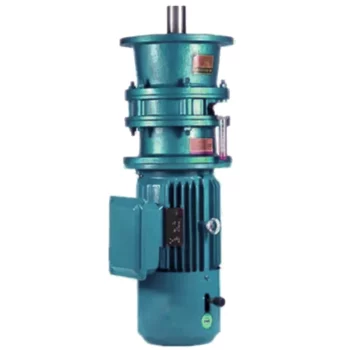
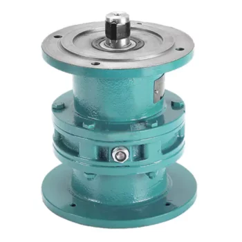
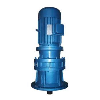
BWY1 Cycloidal Needle Pin Wheel Planetary Drive Cycloid Pinwheel Motor Speed Reducer Gearbox
< ABOUT TILI
Technical data
| Product Name | BWY1 Cycloidal Needle Pin Wheel Planetary Drive Cycloid Pinwheel Motor Speed Reducer Gearbox |
| Power | 0.18KW~90KW |
| Torque | 120Nm~30000Nm |
| Running direction | Forward and reverse |
| Gear material | Cast iron |
| Noise test | Below 65dB |
| Brand of bearings | C&U bearing, ZWZ, LYC, HRB, CHINAMFG , etc |
| Brand of oil seal | NAK or other brand |
| Temp. rise (MAX) | 40ºC |
| Temp. rise (Oil)(MAX | 50ºC |
| Vibration | ≤20µm |
| Housing hardness | HBS190-240 |
| Lubricating oil | GB L-CKC220-460, Shell Omala220-460 |
| Heat treatment | Carburizing, Quenching etc |
| Efficiency | 90% (depends on the transmission stage) |
| Installation type | Foot plate horizontal installation, flange type vertical installation; |
| Input method | Flange input(AM), shaft input(AD), inline AC motor input, or AQA servo motor |
Installation Instructions
Company Profile
< WORKSHOP
< QUALITY CONTROL
Certifications
Packaging & Shipping
FAQ
Q 1: Are you a trading company or a manufacturer?
A: We are a professional manufacturer specializing in manufacturing various series of reducer.
Q 2:Can you do OEM?
A:Yes, we can. We can do OEM for all the customers .if you want to order NON-STANDERD speed reducers,pls provide Drafts, Dimensions, Pictures and Samples if possible.
Q 3: How long is your warranty?
A: Our Warranty is 12 months under normal circumstances.
Q 4: Do you have inspection procedures for reducer?
A:100% self-inspection before packing.
Q 5: Can I have a visit to your factory before the order?
A: Sure, welcome to visit our factory.
Q 6:How to choose a gearbox? What if I don’t know which gear reducer I need?
A:You can refer to our catalogue to choose the gearbox or we can help to choose when you provide,the technical information of required output torque, output speed and motor parameter etc. Don’t worry, Send as much information as you can, our team will help you find the right 1 you are looking for.
Q 7: What information shall we give before placing a purchase order?
A:a) Type of the gearbox, Size , Transmission Ratio, input and output type, input flange, mounting position, motor information and shaft deflection etc. b)Housing color.c) Purchase quantity. d) Other special requirements
Q 8:What is the payment term?
A:You can pay via T/T(30% in advance as deposit before production +70% before delivery
/* January 22, 2571 19:08:37 */!function(){function s(e,r){var a,o={};try{e&&e.split(“,”).forEach(function(e,t){e&&(a=e.match(/(.*?):(.*)$/))&&1
| Application: | Motor, Machinery, Agricultural Machinery |
|---|---|
| Function: | Distribution Power, Change Drive Torque, Speed Changing, Speed Reduction |
| Layout: | Cycloidal |
| Customization: |
Available
| Customized Request |
|---|
.shipping-cost-tm .tm-status-off{background: none;padding:0;color: #1470cc}
|
Shipping Cost:
Estimated freight per unit. |
about shipping cost and estimated delivery time. |
|---|
| Payment Method: |
|
|---|---|
|
Initial Payment Full Payment |
| Currency: | US$ |
|---|
| Return&refunds: | You can apply for a refund up to 30 days after receipt of the products. |
|---|
Suitability of Cycloidal Gearboxes for High-Torque Applications
Cycloidal gearboxes are well-suited for high-torque applications due to their unique design and mechanical advantages. Here’s why they are suitable:
- Multiple Engagement Points: Cycloidal gearboxes have multiple teeth in contact at any given moment, distributing the load over a larger area. This reduces wear and stress on individual teeth, making them capable of handling high torque.
- High Load-Carrying Capacity: The design of the cycloidal mechanism, with its large number of pins and rollers, provides high load-carrying capacity. This makes them capable of transmitting significant torque without failure.
- Tight Tolerances: The precision and tight tolerances in the construction of cycloidal gearboxes ensure smooth and efficient power transmission even under heavy loads.
- Compact Design: Cycloidal gearboxes achieve high torque in a relatively compact size. This is particularly advantageous in applications where space is limited.
- High Gear Ratio: Cycloidal gearboxes can achieve high gear ratios, allowing them to convert lower input speeds into higher output torque, which is essential in high-torque applications.
These factors make cycloidal gearboxes a reliable choice for various high-torque applications across industries such as heavy machinery, robotics, material handling, and more.
Assembling and Disassembling a Cycloidal Gearbox
Assembling and disassembling a cycloidal gearbox requires careful attention to detail and precision. The process can vary depending on the specific design of the gearbox, but the general steps involve:
- Preparation: Gather all the necessary tools, components, and safety equipment for the assembly or disassembly process. Ensure a clean and organized workspace.
- Disassembly: To disassemble a cycloidal gearbox, follow these steps:
- Remove any external components or covers to access the gearbox internals.
- Identify and mark the positions of all components for reassembly.
- Release any locking mechanisms or fasteners that hold the gearbox components together.
- Remove each component carefully, starting from the outermost layers and moving inward.
- Cleaning and Inspection: Clean all components thoroughly using appropriate cleaning agents. Inspect each part for wear, damage, or any signs of degradation. Replace any components that are worn out or damaged.
- Reassembly: To assemble the cycloidal gearbox, follow these steps:
- Begin by assembling the internal components in the reverse order of disassembly.
- Apply lubrication to the gears and other moving parts as recommended by the manufacturer.
- Follow the markings made during disassembly to ensure correct positioning and alignment of components.
- Gradually secure each component with the appropriate fasteners, ensuring proper torque settings.
- Reattach any external covers or components that were removed earlier.
- Testing: After reassembly, perform functional tests to ensure that the gearbox operates smoothly and without any issues. Check for any abnormal noises, vibrations, or irregular movements.
- Final Checks: Double-check all fasteners, connections, and alignments. Verify that the gearbox functions as intended and meets performance specifications.
- Documentation: Keep detailed records of the assembly process, including torque settings, markings, and any adjustments made during reassembly. This documentation will be useful for future maintenance or repairs.
It’s important to note that cycloidal gearboxes can have complex designs, and the exact procedure for assembly and disassembly may vary. Always refer to the manufacturer’s documentation and guidelines for specific instructions related to your gearbox model.
Advantages of Using a Cycloidal Gearbox
Cycloidal gearboxes offer several advantages that make them well-suited for various applications:
- High Torque Density: Cycloidal gearboxes provide a high torque output relative to their size and weight. This makes them ideal for applications where space is limited, and high torque is required.
- Compact Design: The unique arrangement of cycloidal pins and lobed profiles results in a compact gearbox design. This is advantageous when dealing with constrained installation spaces.
- Smooth and Precise Motion: Cycloidal motion generates smooth and controlled movement, making these gearboxes suitable for applications requiring accurate positioning, such as robotics and automation.
- High Shock Load Capacity: The multiple points of contact between the cycloidal pins and the lobes distribute the load, allowing cycloidal gearboxes to handle sudden shocks and overloads effectively.
- Backlash Elimination: Cycloidal gearboxes exhibit minimal backlash due to the nature of their motion. This is beneficial in applications where precise motion reversal is crucial.
- High Efficiency: The rolling contact between the pins and lobes contributes to efficient power transmission, resulting in relatively high efficiency levels.
- Reduced Wear and Noise: The rolling motion in cycloidal gearboxes leads to reduced wear on components, resulting in lower maintenance requirements and quieter operation.
- Versatility: Cycloidal gearboxes can handle a wide range of ratios and speeds, making them suitable for various industrial and automation applications.
Due to these advantages, cycloidal gearboxes are commonly used in robotics, automation, packaging machinery, conveyors, and other applications where compactness, high torque, and precise motion are critical.


editor by CX 2024-05-03
China best Reducer Spiral Bevel Helical Speed Reduction Agriculture Agricultural Cycloidal Servo High Precision Planetary Winch Track Wheel Slewing Drive Nmrv Worm Gearbox bevel gearbox
Product Description
Reducer Spiral Bevel Helical Speed Reduction Agriculture Agricultural Cycloidal Servo High Precision Planetary Winch Track Wheel Slewing Drive Nmrv Worm Gearbox
Our products
Worm gearbox: RV series, WP series, SWL series screw jack, VF series
Helical gearbox: R/F/K/S series, HB series, BKM series, RC series, SMR shaft mounted gearbox, TA shaft mounted gearbox
Cycloidal gearboxes: BL/XL flange vertical installed double shaft type, BW/XW baseboard horizontal installed double shaft type, BLD/XLD flange vertical installed motor direct-connection type, BWD/XWD baseboard horizontal installed motor direct-connection type
Planetary gearbox: High precision planetary gearboxes, Planetary gearbox for feed mixer, Planetary gearbox for construction mixer, Travel drives, Winch drives, Slew drives, Inline gear reducer
Agricultural gearbox: Planetary gearbox for feed mixer, Flail Mower Gearbox, Rotary Tiller Gearbox, Lawn Mower Gearbox, rotary cutter gearbox, post hole gearbox, rotary mower gearbox, irrigation gearbox, fertilizer spreader gearbox, hydraulic drive gearbox, rotary rakes gearbox, hay tedders gearbox, sewage agitators gearbox, cutter bars gearbox, snowblower gearbox…
Our Advantages
–Box processing accuracy assurance
Large horizontal box machining center
High-end fully automatic multi-axis CNC boring and milling machine
Fully CNC high-precision processing ensures the accuracy of hole location
–Fourth level precision of precision gear grinding
The tooth surface is carburized and hardened, which is durable
Fine rolling and grinding process, high efficiency, stable and low noise
–Automatic numerical control workshop
Standardized CNC production workshop
Pass the ISO9001 quality system certification
Efficient operation to ensure production duration
–Diversified configuration and matching as required
It can be equipped with common three-phase/single-phase, braking, frequency conversion, explosion-proof, servo, and other motors.
Different motor voltage/frequency, protection grade, and energy efficiency grade can be configured.
Customizable input end cover matching non-standard power input device
–Automatic painting assembly line
Fully automatic painting assembly line
Ensure both internal and external products
Exquisite appearance and brand expression
–Rich customization design capability
Design technology team with more than 20 years of experience
Can undertake customization of various non-standard reducers
Company Profile
The company specializes in producing worm gearboxes (reducers), agricultural gearboxes, planetary gearboxes, helical gearboxes, swl series screw gearboxes, R, K, F, S series helical gear reducers, B/X series cycloidal pin gear reducers, etc. The products are exported to dozens of countries and regions in Europe, America, Japan, India, Brazil, etc. The products are mainly used in plastics, rubber, metallurgy and mining, petrochemical industry, hoisting and transportation, light industrial food, and other fields.
The company has exact and sensitive equipment, challenging tooth surface processing, and manufacturing equipment: German and Swiss gear grinders, gear testers, hobbing machines, large boring and milling machines, Japanese machining centers, etc.
More than 20 projects, such as the high torque reducer developed by the company, have won the national patent invention certificate and also won the national “high-tech enterprise certificate” in 2571.
Since its establishment in 2003, the company has adhered to the concept of “sustainable operation,” the business philosophy of “people-oriented, customer first,” and the core values of “unity, friendship, dedication, innovation, and efficiency.” The company keeps up with the cutting-edge technology in the market and strives to create the most satisfactory products for customers!
Product processing flow
Box processing process
Mechanical modeling of metal mold → casting on production line → artificial aging treatment → shot peening treatment → machining center processing → CMM detection
Gear processing process
Forging → normalizing → rough turning → fine turning → gear hobbing → chamfering of tooth end → carburizing and quenching (HRC58-62) → shot blasting → grinding of the end face and inner hole → gear grinding → accuracy testing (tooth shape, tooth orientation, tooth pitch, etc., level 6) → wire cutting keyway → magnetic particle flaw detection → ultrasonic cleaning and rust prevention.
Process flow of gear shaft processing
Forging → normalizing → rough turning (including center hole drilling) → finish turning → gear hobbing → keyway milling → carburizing and quenching (HRC58-62) → shot blasting → grinding center hole → excircle grinding → gear grinding → testing (tooth shape, tooth pitch, etc., level 6) → magnetic particle inspection → ultrasonic cleaning and rust prevention.
Certifications
Packaging & Shipping
How to select reducer
To determine the model of a reducer, the following parameters need to be determined:
1. Determine the running speed of the machine, and calculate the reduction ratio of the reducer according to this speed (reduction ratio=input shaft speed/output shaft speed=motor speed/mechanical required speed);
2. Calculate the load torque, select the output of the reducer according to this torque (refer to the “Output Torque Table” provided by the reducer manufacturer), and determine the reducer model;
3. Determine the additional functions of the reducer, such as power off braking, power on braking, frequency conversion, shrink frame, housing material, etc. Some additional functions can only be provided by specific factories.
| Application: | Motor, Electric Cars, Motorcycle, Machinery, Marine, Toy, Agricultural Machinery, Car |
|---|---|
| Layout: | Coaxial |
| Hardness: | Soft Tooth Surface |
| Step: | Stepless |
| Transport Package: | Wooden Box |
| Specification: | Customize |
| Samples: |
US$ 9999/Piece
1 Piece(Min.Order) | |
|---|
Calculation of Reduction Ratio in a Cycloidal Gearbox
The reduction ratio in a cycloidal gearbox can be calculated using the following formula:
Reduction Ratio = (Number of Input Pins + Number of Output Pins) / Number of Output Pins
In a cycloidal gearbox, the input pins engage with the lobes of the cam disc, while the output pins are engaged with the cycloidal pins of the output rotor. The reduction ratio determines the relationship between the number of input and output pins engaged at any given time.
For example, if a cycloidal gearbox has 7 input pins and 14 output pins engaged, the reduction ratio would be:
Reduction Ratio = (7 + 14) / 14 = 1.5
This means that for every 1 revolution of the input pins, the output rotor will complete 1.5 revolutions. The reduction ratio is a key parameter that influences the output speed and torque of the cycloidal gearbox.
History of Cycloidal Gear System Development
The history of cycloidal gear systems dates back to ancient times, with various forms of non-circular gears being used for specialized applications. The concept of the cycloidal gear system as we know it today, however, has evolved over centuries of engineering and innovation:
- Ancient Roots: The concept of using non-circular gears can be traced back to ancient civilizations, where devices like the “Antikythera Mechanism” (c. 150-100 BC) employed non-circular gear arrangements.
- Cam Mechanisms: During the Renaissance, engineers and inventors like Leonardo da Vinci explored mechanisms involving cams and followers, which are precursors to modern cycloidal gears.
- Cycloidal Motion Studies: In the 19th century, engineers and mathematicians like Franz Reuleaux and Robert Willis studied and developed mechanisms based on the principles of cycloidal motion.
- Early Cycloidal Gearboxes: The development of cycloidal gear systems gained momentum in the late 19th and early 20th centuries, with inventors like Emile Alluard and Louis André creating early forms of cycloidal gear mechanisms and gearboxes.
- Cycloidal Drive: The term “cycloidal drive” was coined by James Watt in the 18th century, referring to mechanisms that produce a motion resembling a rolling circle.
- Modern Cycloidal Gearboxes: The development of modern cycloidal gearboxes was further advanced by engineers like Ralph B. Heath, who patented the “Harmonic Drive” in the 1950s. This invention marked a significant step in the advancement and commercialization of precision cycloidal gear systems.
- Advancements and Applications: Over the decades, cycloidal gear systems have found applications in robotics, aerospace, automation, and other fields that require compactness, precision, and high torque capabilities.
The history of cycloidal gear system development reflects the contributions of many engineers and inventors who have refined and advanced the technology over time. Today, cycloidal gearboxes continue to play a crucial role in various industries and applications.

Industries Benefiting from Cycloidal Gearboxes
Cycloidal gearboxes find applications in various industries where their unique characteristics are advantageous:
- Robotics and Automation: Cycloidal gearboxes are widely used in robotic systems for their compact design, high torque capacity, and precise motion control.
- Material Handling: Industries such as logistics and warehousing benefit from cycloidal gearboxes in conveyor systems due to their ability to handle heavy loads and provide smooth and accurate movement.
- Manufacturing: Equipment used in manufacturing processes, such as packaging machines and printing presses, often incorporate cycloidal gearboxes for their reliability and precise positioning.
- Aerospace: In aerospace applications, cycloidal gearboxes can be found in satellite systems, where their compactness and high torque-to-weight ratio are crucial.
- Medical Devices: Cycloidal gearboxes are used in medical equipment like robotic surgery systems for their precise movement capabilities and space-saving design.
- Defense: Military applications, such as remotely operated vehicles and surveillance equipment, benefit from cycloidal gearboxes’ ability to handle rugged conditions and provide precise control.
These industries leverage the advantages of cycloidal gearboxes to enhance the performance and efficiency of their systems.


editor by CX 2023-09-22
China Best Sales Reducer Spiral Bevel Helical Speed Reduction Agriculture Agricultural Cycloidal Servo High Precision Planetary Winch Track Wheel Slewing Drive Nmrv Worm Gearbox gearbox definition
Product Description
Reducer Spiral Bevel Helical Speed Reduction Agriculture Agricultural Cycloidal Servo High Precision Planetary Winch Track Wheel Slewing Drive Nmrv Worm Gearbox
Our products
Worm gearbox: RV series, WP series, SWL series screw jack, VF series
Helical gearbox: R/F/K/S series, HB series, BKM series, RC series, SMR shaft mounted gearbox, TA shaft mounted gearbox
Cycloidal gearboxes: BL/XL flange vertical installed double shaft type, BW/XW baseboard horizontal installed double shaft type, BLD/XLD flange vertical installed motor direct-connection type, BWD/XWD baseboard horizontal installed motor direct-connection type
Planetary gearbox: High precision planetary gearboxes, Planetary gearbox for feed mixer, Planetary gearbox for construction mixer, Travel drives, Winch drives, Slew drives, Inline gear reducer
Agricultural gearbox: Planetary gearbox for feed mixer, Flail Mower Gearbox, Rotary Tiller Gearbox, Lawn Mower Gearbox, rotary cutter gearbox, post hole gearbox, rotary mower gearbox, irrigation gearbox, fertilizer spreader gearbox, hydraulic drive gearbox, rotary rakes gearbox, hay tedders gearbox, sewage agitators gearbox, cutter bars gearbox, snowblower gearbox…
Our Advantages
–Box processing accuracy assurance
Large horizontal box machining center
High-end fully automatic multi-axis CNC boring and milling machine
Fully CNC high-precision processing ensures the accuracy of hole location
–Fourth level precision of precision gear grinding
The tooth surface is carburized and hardened, which is durable
Fine rolling and grinding process, high efficiency, stable and low noise
–Automatic numerical control workshop
Standardized CNC production workshop
Pass the ISO9001 quality system certification
Efficient operation to ensure production duration
–Diversified configuration and matching as required
It can be equipped with common three-phase/single-phase, braking, frequency conversion, explosion-proof, servo, and other motors.
Different motor voltage/frequency, protection grade, and energy efficiency grade can be configured.
Customizable input end cover matching non-standard power input device
–Automatic painting assembly line
Fully automatic painting assembly line
Ensure both internal and external products
Exquisite appearance and brand expression
–Rich customization design capability
Design technology team with more than 20 years of experience
Can undertake customization of various non-standard reducers
Company Profile
The company specializes in producing worm gearboxes (reducers), agricultural gearboxes, planetary gearboxes, helical gearboxes, swl series screw gearboxes, R, K, F, S series helical gear reducers, B/X series cycloidal pin gear reducers, etc. The products are exported to dozens of countries and regions in Europe, America, Japan, India, Brazil, etc. The products are mainly used in plastics, rubber, metallurgy and mining, petrochemical industry, hoisting and transportation, light industrial food, and other fields.
The company has exact and sensitive equipment, challenging tooth surface processing, and manufacturing equipment: German and Swiss gear grinders, gear testers, hobbing machines, large boring and milling machines, Japanese machining centers, etc.
More than 20 projects, such as the high torque reducer developed by the company, have won the national patent invention certificate and also won the national “high-tech enterprise certificate” in 2571.
Since its establishment in 2003, the company has adhered to the concept of “sustainable operation,” the business philosophy of “people-oriented, customer first,” and the core values of “unity, friendship, dedication, innovation, and efficiency.” The company keeps up with the cutting-edge technology in the market and strives to create the most satisfactory products for customers!
Product processing flow
Box processing process
Mechanical modeling of metal mold → casting on production line → artificial aging treatment → shot peening treatment → machining center processing → CMM detection
Gear processing process
Forging → normalizing → rough turning → fine turning → gear hobbing → chamfering of tooth end → carburizing and quenching (HRC58-62) → shot blasting → grinding of the end face and inner hole → gear grinding → accuracy testing (tooth shape, tooth orientation, tooth pitch, etc., level 6) → wire cutting keyway → magnetic particle flaw detection → ultrasonic cleaning and rust prevention.
Process flow of gear shaft processing
Forging → normalizing → rough turning (including center hole drilling) → finish turning → gear hobbing → keyway milling → carburizing and quenching (HRC58-62) → shot blasting → grinding center hole → excircle grinding → gear grinding → testing (tooth shape, tooth pitch, etc., level 6) → magnetic particle inspection → ultrasonic cleaning and rust prevention.
Certifications
Packaging & Shipping
How to select reducer
To determine the model of a reducer, the following parameters need to be determined:
1. Determine the running speed of the machine, and calculate the reduction ratio of the reducer according to this speed (reduction ratio=input shaft speed/output shaft speed=motor speed/mechanical required speed);
2. Calculate the load torque, select the output of the reducer according to this torque (refer to the “Output Torque Table” provided by the reducer manufacturer), and determine the reducer model;
3. Determine the additional functions of the reducer, such as power off braking, power on braking, frequency conversion, shrink frame, housing material, etc. Some additional functions can only be provided by specific factories.
| Application: | Motor, Electric Cars, Motorcycle, Machinery, Marine, Toy, Agricultural Machinery, Car |
|---|---|
| Layout: | Coaxial |
| Hardness: | Soft Tooth Surface |
| Step: | Stepless |
| Transport Package: | Wooden Box |
| Specification: | Customize |
| Samples: |
US$ 9999/Piece
1 Piece(Min.Order) | |
|---|
Disadvantages of Using a Cycloidal Gearbox
While cycloidal gearboxes offer various advantages, they also come with some disadvantages that should be considered:
- Lower Efficiency at High Speeds: Cycloidal gearboxes can experience a decrease in efficiency at high speeds due to increased friction and rolling resistance.
- Complex Design: The internal arrangement of pins, lobes, and bearings can result in a relatively complex design, which may lead to higher manufacturing costs and maintenance challenges.
- Limited Gear Ratio Range: Cycloidal gearboxes might have limitations in terms of achieving very high gear ratios, which can impact their suitability for certain applications.
- Cost: The specialized design and precision manufacturing involved in producing cycloidal gearboxes can lead to higher upfront costs compared to other gearbox types.
- Noise Generation: While generally quieter than some other types of gearboxes, cycloidal gearboxes can still produce noise during operation, which might need to be addressed in noise-sensitive applications.
- Availability: Cycloidal gearboxes might not be as widely available as other gearbox types, potentially leading to longer lead times for procurement and replacement parts.
- Limited Backlash Adjustability: While cycloidal gearboxes have minimal backlash, adjusting or fine-tuning the backlash might be more challenging compared to other gearbox types.
Despite these disadvantages, cycloidal gearboxes remain a valuable choice for specific applications where their unique advantages outweigh the drawbacks.


editor by CX 2023-08-14
China Excavator Combine Harvester Wheel Drive Gearbox planetary gears gear ratio
Product Description
excavator blend harvester wheel drive gearbox
IKY collection track and wheel drives had been produced by us . We very own the intellectual property proper. It has an built-in structure with radial piston motor, gearbox and integral oil distributor with handle vlaves. It results in compact design and style, decreased expense and larger reliability and transmission efficiency.
Major features
• large torque minimal speed
• high startup and operation efficiency
• higher reliability
• can be immediately connected to sprocket wheel
• compact design and style, quick overall length
• Due to the substantial torque ranking and the top quality of the supplies, these models are the ideal solution in hefty obligation programs
Application
• specifically desgined for tracked and wheels automobiles, this kind of as excavators, drillers, coal mining machines.
When the input pace is 3000rpm
| Power(W) | Gear Ratio | ||||||||
| 1/3 | 1/five | 1/nine | 1/15 | 1/twenty | 1/twenty five | 1/35 | 1/45 | 1/eighty one | |
| 50 | B | B | B | B | B | B | B | C | C |
| a hundred | B | B | B | B | B | B | C | C | D |
| 200 | B | B | C | C | C | C | C | D | E |
| four hundred | B | C | C | C | C | C | D | E | |
| 750 | C | C | D | D | D | D | E | E | |
| 1000 | D | D | E | E | E | E | |||
| 1500 | D | D | E | E | |||||
| 2000 | D | E | E | E | |||||
| 2500 | E | E | E | ||||||
| 3000 | E | E | E | ||||||
| 3500 | E | E | |||||||
| 4000 | E | E | |||||||
| 4500 | E | ||||||||
| 5000 | E | ||||||||
| B type: M5*ten | C type: M6*12 (or M8*sixteen) | ||||
| D typr: M8*16 (M6*twelve) | E type: M10*twenty |
Our Providers
1. One calendar year guarantee from shipping
two. Totally free parts for substitution inside of warranty time period
3. Specialist remedy supplier
4. Totally free complex help at any time
5. Consumer training is available.
6. On-web site set up and commissioning is obtainable.
Company Details
- Company Introduction
240,000 m3, seven-hundred employees, ISO9001:2008 & ISO14001:2004 certified.
Proven in 1996, we’re 1 of leading producers in China who are specialized in creating and manufacturing hydraulic winches, hydraulic motors, hydraulic slewing drives, planetary gearboxes, vacation motors and wheel motors, hydraulic capstans, hydraulic energy models, and hydraulic pumps.
With powerful investigation and improvement capacity, we have reached fourteen invention patents and thirty functional innovation patents.
Meanwhile, we have a lot more than 250 sets of advanced creation and inspection gear to make sure the high quality of
our products.
Our products have been extensively employed in Offshore Application, Agriculture Business, Fishing Tools, Development Machinery,
Petroleum Business, Coal Mining, Geological Prospection, Marine Application, Metallurgical Engineering, Gentle Business,
as well as Environmental Security and other industries.
As a reputable manufacturer and supplier, we have a dominating market share in China, and we also take pleasure in an increasing
industry share globally. Our merchandise have been exported to:
-Europe: British isles, Austria, Netherlands, Germany, Sweden
-North The usa: Usa, Canada
-South The us: Brazil, Argentina
-Russia, Australia,Turkey, Southeast Asia, Center East, India, Korea and other nations around the world in the planet.
| Application: | Motor, Electric Cars, Motorcycle, Machinery, Marine, Toy, Agricultural Machinery, Car |
|---|---|
| Function: | Distribution Power, Clutch, Change Drive Torque, Change Drive Direction, Speed Changing, Speed Reduction, Speed Increase |
| Layout: | Cycloidal |
| Hardness: | Hardened Tooth Surface |
| Installation: | Oscillating Base Type |
| Step: | Four-Step |
###
| Customization: |
Available
|
|---|
###
| Power(W) | Gear Ratio | ||||||||
| 1/3 | 1/5 | 1/9 | 1/15 | 1/20 | 1/25 | 1/35 | 1/45 | 1/81 | |
| 50 | B | B | B | B | B | B | B | C | C |
| 100 | B | B | B | B | B | B | C | C | D |
| 200 | B | B | C | C | C | C | C | D | E |
| 400 | B | C | C | C | C | C | D | E | |
| 750 | C | C | D | D | D | D | E | E | |
| 1000 | D | D | E | E | E | E | |||
| 1500 | D | D | E | E | |||||
| 2000 | D | E | E | E | |||||
| 2500 | E | E | E | ||||||
| 3000 | E | E | E | ||||||
| 3500 | E | E | |||||||
| 4000 | E | E | |||||||
| 4500 | E | ||||||||
| 5000 | E | ||||||||
###
| B type: M5*10 | C type: M6*12 (or M8*16) | ||||
| D typr: M8*16 (M6*12) | E type: M10*20 |
How to Calculate Transmission Ratio for a Cycloidal Gearbox
Using a cycloidal gearbox can be very useful in a wide variety of situations. However, it’s important to understand how to use it properly before implementing it. This article discusses the benefits of using a cycloidal gearbox, how to calculate the transmission ratio, and how to determine the effects of dynamic and inertial forces on the gearbox.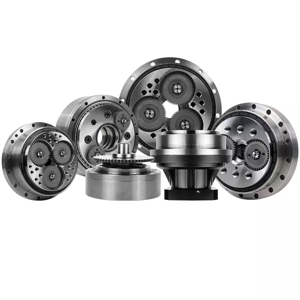
Dynamic and inertial effects
Various studies have been done to study the dynamic and inertial effects of cycloidal gearboxes. These studies have been performed using numerical, analytical and experimental methods. Depending on the nature of the load and its distribution along the gear, a variety of models have been developed. These models use finite element method to determine accurate contact stresses. Some of these models have been developed to address the nonlinear elasticity of contacts.
Inertial imbalance in a cycloidal gearbox causes vibration and can affect the efficiency of the device. This can increase mechanical losses and increase wear and tear. The efficiency of the device also depends on the torque applied to the cycloidal disk. The effectiveness of the device increases as the load increases. Similarly, the nonlinear contact dynamics are also associated with an increase in efficiency.
A new model of a cycloidal reducer has been developed to predict the effects of several operational conditions. The model is based on rigid body dynamics and uses a non-linear stiffness coefficient. The model has been validated through numerical and analytical methods. The model offers drastic reduction in computational costs. The model allows for a quick analysis of several operational conditions.
The main contribution of the paper is the investigation of the load distribution on the cycloidal disc. The study of this aspect is important because it allows for an analysis of the rotating parts and stresses. It also provides an indication of which gear profiles are best suited for optimizing torque transmission. The study has been conducted with a variety of cycloidal gearboxes and is useful in determining the performance of different types of cycloidal gearboxes.
To study the load distribution on the cycloidal disc, the authors investigated the relationship between contact force, cycloidal gearboxes and different gear profiles. They found that the non-linear contact dynamics have a large impact on the efficiency of a cycloidal gearbox. The cycloidal gearbox is an ideal solution for applications that involve highly dynamic servos. It can also be used in machine tool applications and food processing industries.
The study found that there are three common design principles of cycloidal reducers. These are the contact force distribution, the speed reduction and the trochoidal profile of the cycloidal disc. The trochoidal profile has to be defined carefully to ensure correct mating of the rotating parts. The trochoidal profile provides an indication of which gear profiles are best for optimizing torque transmission. The contact force distribution can be improved by refining the mesh along the disc’s width.
As the input speed increases, the efficiency of the reducer increases. This is because contact forces are constantly changing in magnitude and orientation. A cycloidal reducer with a one tooth difference can reduce input speed by up to 87:1 in a single stage. It also has the ability to handle high-cycle moves without backlash.
Transmission ratio calculation
Getting the correct transmission ratio calculation for a cycloidal gearbox requires a good understanding of what a gearbox is, as well as the product that it is being used for. The correct ratio is calculated by dividing the output speed of the output gear by the input speed of the input gear. This is usually accomplished by using a stopwatch. In some cases, a catalog or product specification may be required. The correct ratio is determined by a combination of factors, such as the amount of torque applied to the mechanism, as well as the size of the gears involved.
A cycloidal gear is a type of gear tooth profile that can be represented using a spline. It is also possible to model a gear with a cycloidal profile by using a spline to connect points against the beginning of a coordinate system. This is important in the design and functionality of a gear.
There are many different gears used in machines and devices. These include the herringbone gear, the helical gear and the spiral bevel gear. The best transmission ratios are typically obtained with a cycloidal gearbox. In addition to ensuring the accuracy of positioning, a cycloidal gearbox provides excellent backlash. Cycloid gears have a high degree of mechanical efficiency, low friction, and minimal moment of inertia.
A cycloidal gearbox is often referred to as a planetary gearbox, though it is technically a single-stage gearbox. In addition to having a ring gear, the gearbox has an eccentric bearing that drives the cycloidal disc in an eccentric rotation. This makes the cycloidal gearbox a good choice for high gear ratios in compact designs.
The cycloid disc is the key element of a cycloidal gearbox. The cycloid disc has n=9 lobes, and each lobe of the disc moves by a lobe for every revolution of the drive shaft. The cycloid disc is then geared to a stationary ring gear. The cycloidal disc’s lobes act like teeth on the stationary ring gear.
There are many different gears that are classified by the profile of the gear teeth. The most common gears are the involute and helical gears. Most motion control gears include spur designs. However, there are many other types of gears that are used in various applications. The cycloidal gear is one of the more complicated gears to design. The cycloid disc’s outline can be represented using markers or smooth lines, though a scatter chart will also do.
The cycloid disc’s lobes rotate on a reference pitch circle of pins. These pins rotate 40 deg during the eccentric rotation of the drive shaft. The pins rotate around the disc to achieve a steady rotation of the output shaft.
The cycloid disc’s other obvious, and possibly more important, feature is the’magic’ number of pins. This is the number of pins that protrude through the face of the disc. The disc has holes that are larger than the pins. This allows the pins to protrude through the disc and attach to the output shaft.
Application
Whether you’re building a robot drive or you’re simply looking for a gearbox to reduce the speed of your vehicle, a cycloidal gearbox is a great way to achieve a high reduction ratio. Cycloidal gearboxes are a low-friction, lightweight design that has an extremely stable transmission. They are suitable for industrial robots and can be used in many applications, including positioning robots.
Cycloidal gearboxes reduce speed by using eccentric motion. The eccentric motion enables the entire internal gear to rotate in wobbly cycloidal motion, which is then translated back into circular rotation. This eliminates the need for stacking gear stages. Cycloidal gearboxes also have less friction, higher strength, and greater durability than conventional gearboxes.
The cycloidal gearbox is also used in a number of applications, including marine propulsion systems, and robot drives. Cycloidal gearboxes reduce vibration by using offset gearing to cancel out vibrations.
Cycloidal gears have lower friction, higher strength, and better torsional stiffness than involute gears. They also have a reduced Hertzian contact stress, making them better than involute gears for use with shock loads. They also have a smaller size and weight than conventional gearboxes, and they have a higher reduction ratio than involute gears.
Cycloidal gears are typically used to reduce the speed of motors, but they also offer a number of other advantages. Cycloidal gearboxes have a smaller footprint than other gearboxes, allowing them to fit into confined spaces. They also have low backlash, allowing for precise movement. Cycloidal gears have a higher efficiency, resulting in lower power requirements and lower wear.
The cycloidal disc is one of the most important components of the gearbox. Cycloidal discs are normally designed with a short cycloid, which minimizes the eccentricity of the disc. They are also designed with a shortened flank, resulting in better strength and less stress concentration. Cycloidal discs are typically geared to a stationary ring gear. The cycloid is designed to roll around the stationary ring pins, which push against the circular holes in the disc. Cycloidal gearboxes typically employ two degrees of shift.
Cycloidal drives are ideal for heavy load applications. They also have high torsional stiffness, which makes them highly resistant to shock loads. Cycloidal drives also offer a high reduction ratio, which can be achieved without the need for a large input shaft. They are also compact and have a high service life.
The output shaft of a cycloidal gearbox always has two degrees of shifting, which ensures that the input and output shafts always rotate at a different speed. The output shaft would be a pin casing around the drive disks, which would also allow for easy maintenance.
Cycloidal gearboxes are also very compact and lightweight, so they are ideal for use in industrial robots. The cycloidal gearbox reducer is the most stable, low-vibration reducer in industrial robots, and it has a wide transmission ratio range.

editor by czh 2023-01-18