Product Description
Product Description
Agriculture Machinery Gear Box Agricultural Agri Farm Tractor Mower Bevel Digger Fertilizer Spreader Rotary Tiller Right Angle Pto Shaft Reducer Gearbox
The Agriculture Machinery Gear Box is a high-quality and durable gearbox designed for use in various agricultural applications. This gearbox is specifically engineered to meet the demands of agri-farm tractors, mowers, diggers, fertilizer spreaders, rotary tillers, and other agricultural machinery.
With its bevel gear design, this gearbox ensures smooth and efficient power transmission, allowing for optimal performance and productivity. The right angle PTO shaft reducer gearbox is built to withstand heavy-duty usage, making it ideal for demanding agricultural tasks.
Featuring a robust construction, this gearbox offers exceptional reliability and longevity, reducing the need for frequent maintenance and replacement. Its compact design allows for easy installation and integration into existing agricultural equipment.
Key Features:
- Bevel gear design for smooth power transmission
- Designed for agri-farm tractors, mowers, diggers, fertilizer spreaders, rotary tillers, and more
- Heavy-duty construction for durability
- Compact design for easy installation
Enhance the performance and efficiency of your agricultural machinery with the Agriculture Machinery Gear Box. Invest in this reliable and high-performing gearbox to maximize productivity and minimize downtime.
Product Parameters
| 1. Large output torque |
| 2. Safe, reliable, economical, and durable |
| 3. Stable transmission, quiet operation |
| 4. High modularization design, may equip with various outer power inputs conveniently. The same machine type may equip with various power motors. It is easy to realize the combination and junction between every machine type |
| 5. Form of installation: The position to be installed is not limited |
| 6. High strength, compact the box body of high strength cast iron, gear and gear shaft adopt the gas carbonization, quenching, and fine grinding process, therefore the bearing capacity of unit volume is high |
| 7. Long life: Under the condition of the correct type chosen(including choosing suitable operation parament ) normal operation and maintenance, the life of the main parts speed reducer(except wearing parts)should not be less than 20000 hours |
| 8. Low noise: Because the main parts of the speed reducer are processed, and tested critically, therefore the noise of the |
Detailed Photos
Company Profile
United Metal Products (HangZhou) Co., Ltd. is located in west coast new economic district, HangZhou, China.
Our products exported to the United States, Canada, Brazil, Germany, France, Italy, Denmark, Australia etc for more than 16 years.
We have passed certification of ISO9000, ISO14001, TS16949. etc.
We focus on metal parts including casting parts and machining parts for construction machinery, agricultural machinery, auto parts, railway parts etc.
Machining casting parts, forging parts, aluminum die casting parts etc.
Bar machining parts, shaft etc.
Bolt/nut/washer.
Welding parts, sheet metal part, bending parts etc.
Fin-type radiators.
Our vast experience includes parts ranging from 0.01kg to 1000 kg with annual volumes from 500 up to 200, 000 pieces in industries such as:
Construction – Excavators, Articulating Dump Trucks, Graders, Pavers, Wheel Loaders, Skid Steers, Asphalt Compactors
Agriculture – Tractors, Combines, Sprayers, Seeders, Implement Attachments, Planters, Air Drills, Cultivators, Balers
Material Handling – Forklifts, Reach Trucks, Order Pickers
Aerial Platforms – Scissors Lifts, Telehandlers
Rail/Transportation – Freight Trains
Forestry – Feller Bunchers
Mining – Mining Trucks
/* January 22, 2571 19:08:37 */!function(){function s(e,r){var a,o={};try{e&&e.split(“,”).forEach(function(e,t){e&&(a=e.match(/(.*?):(.*)$/))&&1
| Application: | Motor, Machinery, Marine, Agricultural Machinery |
|---|---|
| Function: | Distribution Power, Clutch, Change Drive Torque, Change Drive Direction, Speed Changing, Speed Reduction, Speed Increase |
| Layout: | Cycloidal |
| Customization: |
Available
| Customized Request |
|---|
.shipping-cost-tm .tm-status-off{background: none;padding:0;color: #1470cc}
|
Shipping Cost:
Estimated freight per unit. |
about shipping cost and estimated delivery time. |
|---|
| Payment Method: |
|
|---|---|
|
Initial Payment Full Payment |
| Currency: | US$ |
|---|
| Return&refunds: | You can apply for a refund up to 30 days after receipt of the products. |
|---|
Calculation of Reduction Ratio in a Cycloidal Gearbox
The reduction ratio in a cycloidal gearbox can be calculated using the following formula:
Reduction Ratio = (Number of Input Pins + Number of Output Pins) / Number of Output Pins
In a cycloidal gearbox, the input pins engage with the lobes of the cam disc, while the output pins are engaged with the cycloidal pins of the output rotor. The reduction ratio determines the relationship between the number of input and output pins engaged at any given time.
For example, if a cycloidal gearbox has 7 input pins and 14 output pins engaged, the reduction ratio would be:
Reduction Ratio = (7 + 14) / 14 = 1.5
This means that for every 1 revolution of the input pins, the output rotor will complete 1.5 revolutions. The reduction ratio is a key parameter that influences the output speed and torque of the cycloidal gearbox.
Patents Associated with Cycloidal Gearbox Designs
Throughout the history of cycloidal gearbox development, several patents have been filed for various designs and applications. Some notable patents include:
- Harmonic Drive: Ralph B. Heath’s patent for the “Harmonic Drive” (US Patent 2,906,143), filed in 1957, is one of the most famous patents related to cycloidal gear systems. This patent introduced the concept of a high-precision reduction gear mechanism using flexible components.
- Cycloidal Drive Mechanism: A patent by James Watt for a “Cycloidal Drive Mechanism” (GB Patent 1812), dating back to the 18th century, is often cited as one of the early references to cycloidal motion and gears.
- Planetary Roller Transmission: US Patent 3,671,927 by C.F. Kafesjian and H. Blumenstock introduced a “Planetary Roller Transmission” in 1972, describing a cycloidal drive mechanism with planetary motion.
- Cycloidal Speed Reducer: A patent for a “Cycloidal Speed Reducer” (US Patent 5,588,583) was granted to Richard J. Pieprzak in 1996, focusing on an improved design of cycloidal gears for various applications.
These patents represent a small sample of the numerous innovations and designs related to cycloidal gear systems that have been patented over the years. Patents play a significant role in protecting and promoting innovation in the field of gearbox technology.
Advantages of Using a Cycloidal Gearbox
Cycloidal gearboxes offer several advantages that make them well-suited for various applications:
- High Torque Density: Cycloidal gearboxes provide a high torque output relative to their size and weight. This makes them ideal for applications where space is limited, and high torque is required.
- Compact Design: The unique arrangement of cycloidal pins and lobed profiles results in a compact gearbox design. This is advantageous when dealing with constrained installation spaces.
- Smooth and Precise Motion: Cycloidal motion generates smooth and controlled movement, making these gearboxes suitable for applications requiring accurate positioning, such as robotics and automation.
- High Shock Load Capacity: The multiple points of contact between the cycloidal pins and the lobes distribute the load, allowing cycloidal gearboxes to handle sudden shocks and overloads effectively.
- Backlash Elimination: Cycloidal gearboxes exhibit minimal backlash due to the nature of their motion. This is beneficial in applications where precise motion reversal is crucial.
- High Efficiency: The rolling contact between the pins and lobes contributes to efficient power transmission, resulting in relatively high efficiency levels.
- Reduced Wear and Noise: The rolling motion in cycloidal gearboxes leads to reduced wear on components, resulting in lower maintenance requirements and quieter operation.
- Versatility: Cycloidal gearboxes can handle a wide range of ratios and speeds, making them suitable for various industrial and automation applications.
Due to these advantages, cycloidal gearboxes are commonly used in robotics, automation, packaging machinery, conveyors, and other applications where compactness, high torque, and precise motion are critical.


editor by CX 2024-05-09
China OEM Motor CE Certified CZPT box Small Precision Planetary Spur transmission Gearbox cycloidal gearbox manufacturers
Product Description
Detailed Photos
Product Parameters
Note : It’s just the typical technical data for you reference, The specification such as voltage, speed, torque, shaft can be customized by your needs. Please contact us for more details. Thanks.
Company Profile
FAQ
Q: What’re your main products?
A: We currently produce Brushed Dc Motors, Brushed Dc Gear Motors, Planetary Dc Gear Motors, Brushless Dc Motors, Stepper motors, Ac Motors and High Precision Planetary Gear Box etc. You can check the specifications for above motors on our website and you can email us to recommend needed motors per your specification too.
Q: How to select a suitable motor?
A:If you have motor pictures or drawings to show us, or you have detailed specs like voltage, speed, torque, motor size, working mode of the motor, needed lifetime and noise level etc, please do not hesitate to let us know, then we can recommend suitable motor per your request accordingly.
Q: Do you have a customized service for your standard motors?
A: Yes, we can customize per your request for the voltage, speed, torque and shaft size/shape. If you need additional wires/cables soldered on the terminal or need to add connectors, or capacitors or EMC we can make it too.
Q: Do you have an individual design service for motors?
A: Yes, we would like to design motors individually for our customers, but it may need some mold developing cost and design charge.
Q: What’s your lead time?
A: Generally speaking, our regular standard product will need 15-30days, a bit longer for customized products. But we are very flexible on the lead time, it will depend on the specific orders.
Please contact us if you have detailed requests, thank you !
| Application: | Motor, Machinery |
|---|---|
| Function: | Speed Changing, Speed Reduction |
| Layout: | Cycloidal |
| Hardness: | Hardened Tooth Surface |
| Installation: | Vertical Type |
| Step: | Three-Step |
| Customization: |
Available
| Customized Request |
|---|
How to Use a Cyclone Gearbox
Often, a cycloidal gearbox is used in order to achieve a torque transfer from a motor or pump. This type of gearbox is often a common choice as it has a number of advantages over a regular gearbox. Its main advantage is that it is easy to make, which means that it can be incorporated into a variety of applications. However, if you want to use a cycloidal gearbox, there are a few things that you need to know. These include the operation principle, the structure and the dynamic and inertial effects that come with it.
Dynamic and inertial effects
Several studies have been carried out on the static and dynamic properties of cycloidal gears. The study of these effects is beneficial in assisting optimal design of cycloidal speed reducers.
In this paper, the dynamic and inertial effects of a two-stage cycloidal speed reducer have been investigated using the CZPT program package. Moreover, a new model for cycloidal reducers based on non-linear contact dynamics has been developed. The new model aims to predict several operational conditions.
The normal excitation contact force for the cycloid discs of the first and second stage is very similar. However, the total deformation at the contact point is different. This effect is mainly due to the system’s own oscillations. The cycloid discs of the second stage turn around the ring gear roller with a 180deg angle. This angle is a significant contributor to the torque loads. The total excitation force on the cycloid discs of first and second stage is 1848 N and 2068.7 N, respectively.
In order to analyze the contact stress, different gear profiles were investigated. The mesh density was considered as an important design criterion. It was found that a bigger hole reduces the material content of the cycloidal disc and results in more stresses.
Moreover, it is possible to reduce the contact forces in a more efficient manner by changing the geometric parameters. This can be done by mesh refinement along the disc width. The cycloidal disc has the greatest influence on the output results.
The efficiency of a cycloidal drive increases with the increase in load. The efficiency of a cycloidal reducer also depends on the eccentricity of the input shaft and the cycloidal plate. The efficiency curve for small loads is linear. However, for the larger loads, the efficiency curve becomes more non-linear. This is because the stiffness of the cycloid reducer increases as the load increases.
Structure
Despite the fact that it looks like a complicated engineering puzzle, the construction of a cycloidal gearbox is actually quite simple. The key elements are the base, the load plate and the thrust bearing. All these elements work together to create a stable, compact gearbox.
The base is a circular section with several cylindrical pins around its outer edge. The pins are fixed on a fixed ring that holds them in a circular path. The ring serves as a reference circle. The circle’s size is approximately 5mm in diameter.
The load plate is a series of threaded screw holes. These are arranged 15mm away from the center. These are used to anchor external structures. The load plate must be rotated around the X and Y axis.
The thrust bearing is placed on top of the load plate. The bearing is made of an internal diameter of 35mm and an external diameter of 52mm. It is used to allow rotation around the Z axis.
The cycloidal disc is the centerpiece of the cycloidal gearbox. The disc has holes for the pins that drive the output shaft. The holes are larger than those used in output roller pins. The disc also has a reduced eccentricity.
The pins are attached to the cycloidal disc by rolling pins. The pins are made of a material that provides mechanical support for the drive during high-torque situations. The pins have a 9mm external diameter. The disc has a number of lobes and is rotated by one lobe per shaft revolution.
The cycloidal gearbox also has a top cover that helps keep the components together. The cover has a pocket for tools. The top cover also has threads that screw into the casing.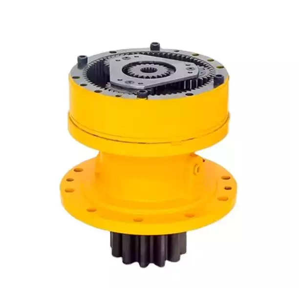
Operation principle
Among many types of gear transmissions, cycloidal gearboxes are used in heavy machinery and multi-axis robots. They are highly effective, compact and capable of high ratios. In addition, they have an overload capability.
Cycloid disks are driven by eccentric shafts that rotate around fixed ring pins. Roller pins of the pin disc engage with holes in the cycloidal disc. These roller pins drive the pin disc and the pin disc transfers the motion to the output shaft.
Unlike conventional gear drives, cycloidal drives have low backlash and high torsional stiffness. They are ideally suited to heavy loads and all drive technologies. The lower mass and compact design of the cycloidal disk also contributes to its high efficiency and positioning accuracy.
The cycloidal disc plays a central role in the gearbox kinematics. It rotates around a fixed ring in a circle. When the disc is pushed against the ring gear, the pins engage with the disc and the roller pins rotate around the pins. This rotating motion generates vibration, which travels through the driven shafts.
Cycloid discs are typically designed with a short cycloid, so that the eccentricity is minimized. This reduces unbalance forces at high speeds. Ideally, the number of lobes on the cycloid is smaller than the number of surrounding pins. This reduces the amount of Hertzian contact stress.
Unlike planetary gears, cycloidal gears have high accuracy and are capable of withstanding shock loads. They also experience low friction and less wear on tooth flanks. They also have higher efficiency and load capacity.
Cycloid gears are generally more difficult to manufacture than involute gears. Cycloid gears are not suitable for stacking gear stages. They require extreme accuracy for manufacturing. However, their smaller size and low backlash, high torsional stiffness, and low vibration make them ideal for use in heavy machines.
Involute gear tooth profile
Almost all gears are manufactured with an involute gear tooth profile. Cycloid gears are also produced with this profile. Compared with involute gears, cycloid gears are stronger and can transmit more power. However, they can also be more difficult to manufacture. This makes them costlier.
The involute gear tooth profile is a smooth curve. It is derived from the involute curve of a circle. A tangent to the base circle is the normal at any point of an involute.
This curve has properties that allow the involute gear teeth to transfer motion in perpendicular direction. It is also the path traced by the end of the string unwrapping from a cylinder.
An involute profile has the advantage of being easy to manufacture. It also allows for smooth meshing despite misalignment of the centre distance. This profile is also preferred over a cycloid tooth profile, but it is not the best in every regard.
Cycloid gear teeth are also made of two curves. Unlike involute teeth, cycloid gear teeth have a consistent radius. Cycloid gears are less likely to produce noise. But they are also more expensive to manufacture.
Involute teeth are easier to manufacture because they have only one curve. Cycloid gears can also be made with a rack type cutter. This makes them cheaper to manufacture. However, they require an expert design. They can also be manufactured with a gear shaper that includes a pinion cutter.
The tooth profiles that satisfy the law of gear-tooth action are sometimes called conjugate profiles. The involute profile is the most common of these. It allows for constant torque transmission.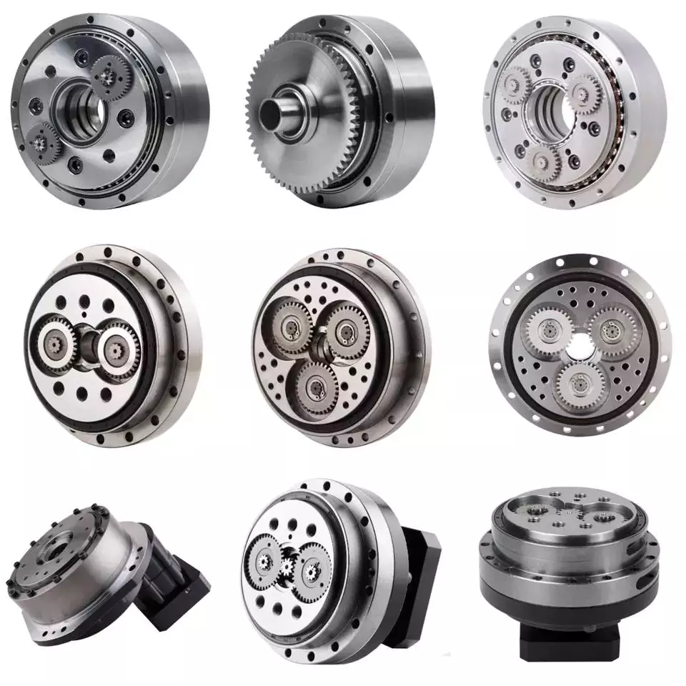
Backlash
Typically, cycloidal drives provide a high ratio of transmission with no backlash. This is because the cycloid disc is driven by an eccentric shaft. During rotation, the cycloid disc rotates around a fixed ring. This ring also rotates independently of the center of gravity.
The cycloid disc is typically shortened to reduce the eccentricity. This helps to minimize the unbalance forces that may occur at high speeds. The cycloid also offers a larger gear ratio than traditional gears. This provides a better positional accuracy.
Cycloid drives also have a high torsional stiffness. This provides greater torsional resilience and shock load capabilities. This is important for a number of reasons, such as in heavy-duty applications.
Cycloid drives also have lower mass. These benefits make them ideally suited for all drive technologies. The design also allows for higher torsional stiffness and service life. These drives also have a much smaller profile.
Cycloid drives are also used to reduce speed. Because of the high torsional stiffness of the cycloid, they also have high positioning accuracy.
Cycloid drives are well-suited to a variety of applications, including electric motors, generators, and pump motors. They are also highly resistant to shock loads, which is important in a variety of applications. This design is ideal for applications that require a large transmission ratio in a compact design.
Cycloid drives also have the advantage of minimizing the clearance between the mating components. This helps to eliminate interference and ensure a positive fit. This is particularly important in gearboxes. It also allows for the use of a load cell and potentiometer to determine the backlash of the gearbox.

editor by CX 2023-04-28
China Manufacturers Sale Gear Box 1.2L Car Engine CN100-LMU Transmission Gearbox For Wuling gearbox assembly
OE NO.: CN100-LMU
Year: 2571-, 2008-
Model: RONGGUANG MPV, HXHV P308 Uc 208 P314 Ucfl204 Uc205 F212 Ucf212 Ucf 212 205 Ucf218 P216 Uc207 Ucp 212 Ucf201 205 Fc212 Pillow Block Bearing XIHU (WEST LAKE) DIS.ANG S MPV
Auto Fitment: XIHU (WEST LAKE) DIS. (SGMW)
Warranty: 1 Calendar year
Automobile Design: For Xihu (West Lake) Dis. HongGuang/RongGuang
Size: Regular, 70*fifty*40 cm
Solution Identify: Transmission Equipment Box
Gearing Arrangement: Cycloidal
Top quality: one hundred% Tested
Packing: Neutral Packing
Software: Car Transmission Components
Other Types: Hiace/22R/14B/ Gearbox For Toyota
Supply: 1-7Working Times
Displacement: 1.2L
Gross Fat: 23kg
Certification: TUV
Packaging Specifics: 1. Regular carton packing or wooden box packing or neutral packing2. In accordance to customers’ needsManufacturers Sale Gear Box 1.2L Automobile Motor CN100-LMU Transmission Gearbox For Xihu (West Lake) Dis.
Port: ZheJiang ZheJiang HangZhou HangZhou
Items Description
| Product identify | Manufacturers Sale Equipment Box 1.2L Automobile Engine CN100-LMU Transmission Gearbox For Xihu (West Lake) Dis. | ||||||
| Car Fitment | For Xihu (West Lake) Dis. | ||||||
| Type | Transmission Gearbox | ||||||
| Output Torque | 350Nm | ||||||
| Output Speed | 600~1500rpm | ||||||
| Displacement | 1.2L | ||||||
| Warranty | 12 Months | ||||||
| Package | Carton/Wooeden | ||||||
| Material | Aluminum & 60004-4 gearbox makers Solid iron | ||||||
| Manufacturer | Ziptek | ||||||
Main Products Organization Profile Our Rewards Packaging & Cargo Personalized Assembly Other Webpages
The Different Types of Gearboxes
There are many different types of gearboxes. Some brands have more than one type. In this article, we’ll discuss the planetary gearbox, the worm reduction gearbox, the shaft mounted gearbox, and the one speed gearbox. This article will also help you determine which type of gearbox is best for your vehicle. And don’t worry if you don’t know the terminology yet. We’ll explain each type in detail so that you know what you’re getting yourself into.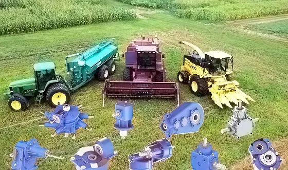
Planetary gearbox
Planetary gears have many advantages. The multiple gears in a planetary gearbox mesh simultaneously during operation. As such, they provide high efficiency and transmit high transmittable torque. These gears are widely used in various industries and are resistant to high shock loads and demanding conditions. CZPT is one of the companies that offer planetary gearboxes. Its products do not require special tools for assembly, and its scalable design minimizes safety stock.
Among the numerous benefits of planetary gearing is its compactness and lightweight. As such, it is suitable for wide applications with space and weight constraints. However, to truly appreciate its benefits, it is necessary to understand its mechanisms. Here are some of the most common details about planetary gearing:
The planetary gearbox has two mounted gears: an input shaft and an output shaft. Each gear has multiple teeth that are attached to a carrier and rotate with the input shaft. The carrier is connected to the output shaft. A planetary gear is mounted on both gears via a carrier. The carrier rotates in order to drive the planetary gear. The sun gear is often the input gear. The other gear is called the outer gear.
Planetary gearboxes are highly customizable. The size, mounting, and housing options vary, as do the reduction ratios and input speeds. Different types can be manufactured for different applications and include options such as electrical or mechanical preload. The final design of a planetary gearbox can be highly customized, based on the specifications of the application. By combining engineering excellence and ongoing innovation, planetary gearboxes provide years of trouble-free operation.
A planetary gearbox can be either an electric motor or a manual one. The latter has more features than the former, and can be used in applications where space is an issue. The primary features of a planetary gearbox include its backlash, torque, and ratio. Secondary features include noise, corrosion resistance, and construction. A planetary gearbox is a highly versatile gearbox that can drive anything from simple machinery to advanced electrical systems.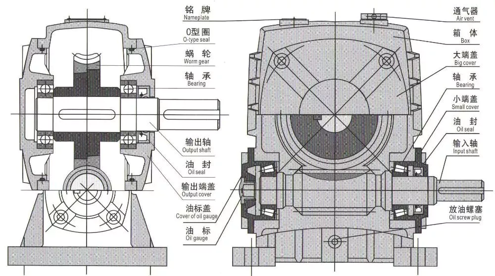
Worm reduction gearbox
The global worm reduction gearbox market report compiles key insights from the industry to help you improve your business strategy. This report will help you create a comprehensive business document that will enhance your company’s competitive edge. To obtain this report, visit our website now! Read our latest report to find out what you can expect from the global worm reduction gearbox market. Alternatively, request a sample copy for more details. Here is a sneak peek of the report:
Worm gears are made with different thread counts and are usually not matched with the CZPT standard. In general, a single thread worm should be used with a single thread worm. Worm gears have either right or left threads, and their thread count will be different as well. This type of gear is used to reduce the speed of a rotating shaft. The speed reduction ratio will be about 50 percent if the worms have the same thread count as the CZPT gears.
The standard gear set transfers power at the peak load point of a tooth, called the pitchline. The worm gear moves slowly against the wheel’s metal surface. The worm gear is also more complex than the standard gear because the worm is sliding rather than rolling. Worm gears are hard to lubricate. Moreover, the sliding contact between the gear and worm increases the complexity of the gear set. They can be a great solution for applications where noise is a significant factor.
The axial pitch and circular pitch of the worm are equal. The ratio of these two indices determines the speed of transmission. For a worm reduction gearbox to work, the axial pitch and the circular pitch must match. The pitch angle of a worm can either be left-handed or right-handed. The lead of a worm is the distance one thread travels in one revolution. The lead angle is the angle tangent to the thread helix of the cylinder’s pitch. When a worm mesh is reversed, the majority of the mesh will be on the receding arc.
Worm gears generate more heat than their counterparts, so it is important to choose a worm reduction gearbox carefully. You will want to choose the material and amount of lubricating oil carefully. Worm gears are generally made of tin bronze. The paired worms are hardened to HRC45-55. In general, they are durable, lasting up to ten years. But they will wear out – and they wear out – so you may want to consider some other factors.
Shaft-mounted gearbox
Shaft-mounted gearboxes are designed for a variety of mining and quarry applications. Their high reliability and low maintenance make them an excellent choice in these types of applications. Shaft-mounted gearboxes also feature an optional backstop device that prevents the unit from rotating in one direction. This makes them an excellent choice for applications where alignment accuracy is an issue. Here are some of the benefits of using a shaft-mounted gearbox:
Shaft-mounted gearboxes are typically constructed of aluminium, and come in sizes ranging from 050 to 125. They feature a variety of reduction ratios and ensure optimum efficiency in all operating conditions. New S series sizes, 140 and 150, extend the application range of shaft-mounted gearmotors. They are both backed by a two-year warranty. For even greater peace of mind, Shaft-mounted gearboxes are available with a range of warranty options.
The most common applications for a Shaft-mounted gearbox include traction-driven applications where a low-speed shaft is required for operation. They also are suitable for applications without a foundation, where the motor is mounted next to the reducer. To prevent the gear drive from rotating, a torque arm is attached between the motor and the shaft. Small-sized shaft-mounted gear drives are usually made without motor mount kits, which can make them an excellent choice for conveying light loads.
Another important feature of a Shaft-mounted gearbox is its mounting position. The reduced motion through the drive is redirected through the shaft, creating additional forces. These additional forces can affect the performance of the gearbox, causing vibrations and noise. Consequently, it is important to replace worn or damaged belts on a regular basis. Further, shaft-mounted gearboxes can be affected by problems with other components and amplify vibrations.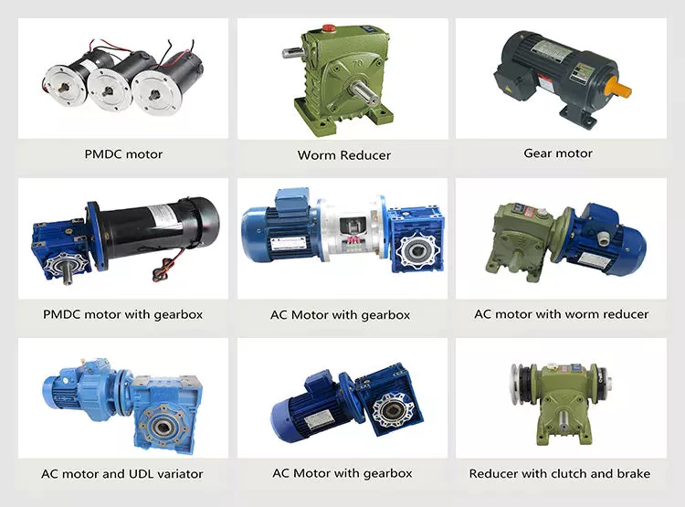
1 speed gearbox
CZPT Group Components produces one speed gearboxes. These transmissions are produced in the CZPT Group’s Kassel plant. They are compact and robust, and are designed for easy integration. The Bosch Rexroth GD1 one-speed gearbox is easy to install horizontally or vertically. The Plug and Drive system integrates the gearbox with the existing cooling system. There are many other benefits to this gearbox.
With an ID.3 electric drive motor, the maximum torque is delivered at 16,000 rpm. This single-speed transmission offers high power density and excellent noise-reduction, making it ideal for electric vehicles. The e-drive motor is extremely quiet and requires precision manufacturing. The e-drive motor also enables a wide range of driving conditions. It can reverse when needed, and reaches its maximum speed at 16,000.
The single-speed gearbox is a standard feature on most electric vehicles. Some electric vehicles, such as the Porsche Taycan, will be equipped with a two-speed gearbox. This gearbox offers more top speed and range, but it is more complex than a standard single-speed gearbox. CZPT doesn’t need to add complexity to its electric vehicles. After all, a 355 horsepower family wagon is not likely to need a dual-speed gearbox.
In addition to simplifying the transmission, the patent claims also address improvements in structural design. Fig. 5 shows a schematic representation of a transmission 50′, wherein gear sets Z1 and Z4 are exchanged between partial transmissions. This switch matrix also reflects the synchronized gears and lastshelf gears. Hydraulically betatigte Lamellenkupplungen (HBA) also form a last-shelf gear.
Another advantage of the patent claim is that it offers numerous functional freedoms, which is especially valuable in the design of an automobile. One of the patent claims identifies a tosatzlicher middle gear that allows a driver to switch between second and third gears, with a single gearbox. In a conventional one-speed transmission, the tosatzlicher middle gear is attached to the second and first part gearbox. The latter has a second and third gear.


editor by czh 2023-02-17