Product Description
Product Description
Agriculture Machinery Gear Box Agricultural Agri Farm Tractor Mower Bevel Digger Fertilizer Spreader Rotary Tiller Right Angle Pto Shaft Reducer Gearbox
The Agriculture Machinery Gear Box is a high-quality and durable gearbox designed for use in various agricultural applications. This gearbox is specifically engineered to meet the demands of agri-farm tractors, mowers, diggers, fertilizer spreaders, rotary tillers, and other agricultural machinery.
With its bevel gear design, this gearbox ensures smooth and efficient power transmission, allowing for optimal performance and productivity. The right angle PTO shaft reducer gearbox is built to withstand heavy-duty usage, making it ideal for demanding agricultural tasks.
Featuring a robust construction, this gearbox offers exceptional reliability and longevity, reducing the need for frequent maintenance and replacement. Its compact design allows for easy installation and integration into existing agricultural equipment.
Key Features:
- Bevel gear design for smooth power transmission
- Designed for agri-farm tractors, mowers, diggers, fertilizer spreaders, rotary tillers, and more
- Heavy-duty construction for durability
- Compact design for easy installation
Enhance the performance and efficiency of your agricultural machinery with the Agriculture Machinery Gear Box. Invest in this reliable and high-performing gearbox to maximize productivity and minimize downtime.
Product Parameters
| 1. Large output torque |
| 2. Safe, reliable, economical, and durable |
| 3. Stable transmission, quiet operation |
| 4. High modularization design, may equip with various outer power inputs conveniently. The same machine type may equip with various power motors. It is easy to realize the combination and junction between every machine type |
| 5. Form of installation: The position to be installed is not limited |
| 6. High strength, compact the box body of high strength cast iron, gear and gear shaft adopt the gas carbonization, quenching, and fine grinding process, therefore the bearing capacity of unit volume is high |
| 7. Long life: Under the condition of the correct type chosen(including choosing suitable operation parament ) normal operation and maintenance, the life of the main parts speed reducer(except wearing parts)should not be less than 20000 hours |
| 8. Low noise: Because the main parts of the speed reducer are processed, and tested critically, therefore the noise of the |
Detailed Photos
Company Profile
United Metal Products (HangZhou) Co., Ltd. is located in west coast new economic district, HangZhou, China.
Our products exported to the United States, Canada, Brazil, Germany, France, Italy, Denmark, Australia etc for more than 16 years.
We have passed certification of ISO9000, ISO14001, TS16949. etc.
We focus on metal parts including casting parts and machining parts for construction machinery, agricultural machinery, auto parts, railway parts etc.
Machining casting parts, forging parts, aluminum die casting parts etc.
Bar machining parts, shaft etc.
Bolt/nut/washer.
Welding parts, sheet metal part, bending parts etc.
Fin-type radiators.
Our vast experience includes parts ranging from 0.01kg to 1000 kg with annual volumes from 500 up to 200, 000 pieces in industries such as:
Construction – Excavators, Articulating Dump Trucks, Graders, Pavers, Wheel Loaders, Skid Steers, Asphalt Compactors
Agriculture – Tractors, Combines, Sprayers, Seeders, Implement Attachments, Planters, Air Drills, Cultivators, Balers
Material Handling – Forklifts, Reach Trucks, Order Pickers
Aerial Platforms – Scissors Lifts, Telehandlers
Rail/Transportation – Freight Trains
Forestry – Feller Bunchers
Mining – Mining Trucks
/* January 22, 2571 19:08:37 */!function(){function s(e,r){var a,o={};try{e&&e.split(“,”).forEach(function(e,t){e&&(a=e.match(/(.*?):(.*)$/))&&1
| Application: | Motor, Machinery, Marine, Agricultural Machinery |
|---|---|
| Function: | Distribution Power, Clutch, Change Drive Torque, Change Drive Direction, Speed Changing, Speed Reduction, Speed Increase |
| Layout: | Cycloidal |
| Customization: |
Available
| Customized Request |
|---|
.shipping-cost-tm .tm-status-off{background: none;padding:0;color: #1470cc}
|
Shipping Cost:
Estimated freight per unit. |
about shipping cost and estimated delivery time. |
|---|
| Payment Method: |
|
|---|---|
|
Initial Payment Full Payment |
| Currency: | US$ |
|---|
| Return&refunds: | You can apply for a refund up to 30 days after receipt of the products. |
|---|
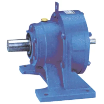
Calculation of Reduction Ratio in a Cycloidal Gearbox
The reduction ratio in a cycloidal gearbox can be calculated using the following formula:
Reduction Ratio = (Number of Input Pins + Number of Output Pins) / Number of Output Pins
In a cycloidal gearbox, the input pins engage with the lobes of the cam disc, while the output pins are engaged with the cycloidal pins of the output rotor. The reduction ratio determines the relationship between the number of input and output pins engaged at any given time.
For example, if a cycloidal gearbox has 7 input pins and 14 output pins engaged, the reduction ratio would be:
Reduction Ratio = (7 + 14) / 14 = 1.5
This means that for every 1 revolution of the input pins, the output rotor will complete 1.5 revolutions. The reduction ratio is a key parameter that influences the output speed and torque of the cycloidal gearbox.
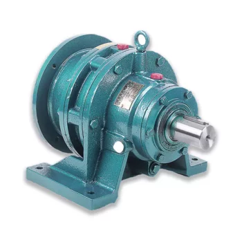
Patents Associated with Cycloidal Gearbox Designs
Throughout the history of cycloidal gearbox development, several patents have been filed for various designs and applications. Some notable patents include:
- Harmonic Drive: Ralph B. Heath’s patent for the “Harmonic Drive” (US Patent 2,906,143), filed in 1957, is one of the most famous patents related to cycloidal gear systems. This patent introduced the concept of a high-precision reduction gear mechanism using flexible components.
- Cycloidal Drive Mechanism: A patent by James Watt for a “Cycloidal Drive Mechanism” (GB Patent 1812), dating back to the 18th century, is often cited as one of the early references to cycloidal motion and gears.
- Planetary Roller Transmission: US Patent 3,671,927 by C.F. Kafesjian and H. Blumenstock introduced a “Planetary Roller Transmission” in 1972, describing a cycloidal drive mechanism with planetary motion.
- Cycloidal Speed Reducer: A patent for a “Cycloidal Speed Reducer” (US Patent 5,588,583) was granted to Richard J. Pieprzak in 1996, focusing on an improved design of cycloidal gears for various applications.
These patents represent a small sample of the numerous innovations and designs related to cycloidal gear systems that have been patented over the years. Patents play a significant role in protecting and promoting innovation in the field of gearbox technology.
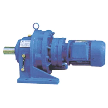
Advantages of Using a Cycloidal Gearbox
Cycloidal gearboxes offer several advantages that make them well-suited for various applications:
- High Torque Density: Cycloidal gearboxes provide a high torque output relative to their size and weight. This makes them ideal for applications where space is limited, and high torque is required.
- Compact Design: The unique arrangement of cycloidal pins and lobed profiles results in a compact gearbox design. This is advantageous when dealing with constrained installation spaces.
- Smooth and Precise Motion: Cycloidal motion generates smooth and controlled movement, making these gearboxes suitable for applications requiring accurate positioning, such as robotics and automation.
- High Shock Load Capacity: The multiple points of contact between the cycloidal pins and the lobes distribute the load, allowing cycloidal gearboxes to handle sudden shocks and overloads effectively.
- Backlash Elimination: Cycloidal gearboxes exhibit minimal backlash due to the nature of their motion. This is beneficial in applications where precise motion reversal is crucial.
- High Efficiency: The rolling contact between the pins and lobes contributes to efficient power transmission, resulting in relatively high efficiency levels.
- Reduced Wear and Noise: The rolling motion in cycloidal gearboxes leads to reduced wear on components, resulting in lower maintenance requirements and quieter operation.
- Versatility: Cycloidal gearboxes can handle a wide range of ratios and speeds, making them suitable for various industrial and automation applications.
Due to these advantages, cycloidal gearboxes are commonly used in robotics, automation, packaging machinery, conveyors, and other applications where compactness, high torque, and precise motion are critical.


editor by CX 2024-05-09
China wholesaler Gearbox with Auxiliary Transmission and Transfer Case Assembly for Tractor Dump Truck 4X4 4WD with Great quality
Product Description
Product Description
Gearbox with Auxiliary Transmission and Transfer Case Assembly
for Tractor Truck 4WD 4X4
Company Profile
Our Advantages
Certifications
Exhibition
Packaging & Shipping
| Application: | Motor, Electric Cars, Motorcycle, Machinery, Marine, Agricultural Machinery, Car |
|---|---|
| Function: | Distribution Power, Change Drive Torque, Change Drive Direction, Speed Changing, Speed Reduction, Speed Increase |
| Layout: | Cycloidal |
| Hardness: | Hardened Tooth Surface |
| Installation: | Torque Arm Type |
| Step: | Four-Step |
| Samples: |
US$ 800/Piece
1 Piece(Min.Order) | |
|---|
| Customization: |
Available
| Customized Request |
|---|
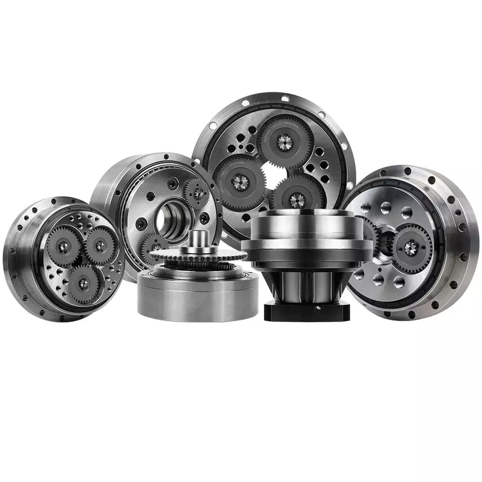
How to Calculate Transmission Ratio for a Cycloidal Gearbox
Using a cycloidal gearbox can be very useful in a wide variety of situations. However, it’s important to understand how to use it properly before implementing it. This article discusses the benefits of using a cycloidal gearbox, how to calculate the transmission ratio, and how to determine the effects of dynamic and inertial forces on the gearbox.
Dynamic and inertial effects
Various studies have been done to study the dynamic and inertial effects of cycloidal gearboxes. These studies have been performed using numerical, analytical and experimental methods. Depending on the nature of the load and its distribution along the gear, a variety of models have been developed. These models use finite element method to determine accurate contact stresses. Some of these models have been developed to address the nonlinear elasticity of contacts.
Inertial imbalance in a cycloidal gearbox causes vibration and can affect the efficiency of the device. This can increase mechanical losses and increase wear and tear. The efficiency of the device also depends on the torque applied to the cycloidal disk. The effectiveness of the device increases as the load increases. Similarly, the nonlinear contact dynamics are also associated with an increase in efficiency.
A new model of a cycloidal reducer has been developed to predict the effects of several operational conditions. The model is based on rigid body dynamics and uses a non-linear stiffness coefficient. The model has been validated through numerical and analytical methods. The model offers drastic reduction in computational costs. The model allows for a quick analysis of several operational conditions.
The main contribution of the paper is the investigation of the load distribution on the cycloidal disc. The study of this aspect is important because it allows for an analysis of the rotating parts and stresses. It also provides an indication of which gear profiles are best suited for optimizing torque transmission. The study has been conducted with a variety of cycloidal gearboxes and is useful in determining the performance of different types of cycloidal gearboxes.
To study the load distribution on the cycloidal disc, the authors investigated the relationship between contact force, cycloidal gearboxes and different gear profiles. They found that the non-linear contact dynamics have a large impact on the efficiency of a cycloidal gearbox. The cycloidal gearbox is an ideal solution for applications that involve highly dynamic servos. It can also be used in machine tool applications and food processing industries.
The study found that there are three common design principles of cycloidal reducers. These are the contact force distribution, the speed reduction and the trochoidal profile of the cycloidal disc. The trochoidal profile has to be defined carefully to ensure correct mating of the rotating parts. The trochoidal profile provides an indication of which gear profiles are best for optimizing torque transmission. The contact force distribution can be improved by refining the mesh along the disc’s width.
As the input speed increases, the efficiency of the reducer increases. This is because contact forces are constantly changing in magnitude and orientation. A cycloidal reducer with a one tooth difference can reduce input speed by up to 87:1 in a single stage. It also has the ability to handle high-cycle moves without backlash.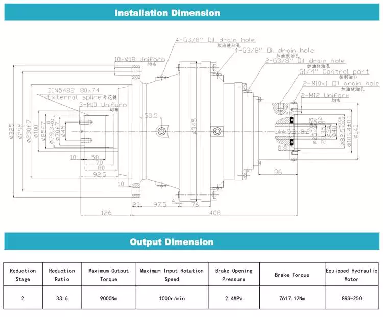
Transmission ratio calculation
Getting the correct transmission ratio calculation for a cycloidal gearbox requires a good understanding of what a gearbox is, as well as the product that it is being used for. The correct ratio is calculated by dividing the output speed of the output gear by the input speed of the input gear. This is usually accomplished by using a stopwatch. In some cases, a catalog or product specification may be required. The correct ratio is determined by a combination of factors, such as the amount of torque applied to the mechanism, as well as the size of the gears involved.
A cycloidal gear is a type of gear tooth profile that can be represented using a spline. It is also possible to model a gear with a cycloidal profile by using a spline to connect points against the beginning of a coordinate system. This is important in the design and functionality of a gear.
There are many different gears used in machines and devices. These include the herringbone gear, the helical gear and the spiral bevel gear. The best transmission ratios are typically obtained with a cycloidal gearbox. In addition to ensuring the accuracy of positioning, a cycloidal gearbox provides excellent backlash. Cycloid gears have a high degree of mechanical efficiency, low friction, and minimal moment of inertia.
A cycloidal gearbox is often referred to as a planetary gearbox, though it is technically a single-stage gearbox. In addition to having a ring gear, the gearbox has an eccentric bearing that drives the cycloidal disc in an eccentric rotation. This makes the cycloidal gearbox a good choice for high gear ratios in compact designs.
The cycloid disc is the key element of a cycloidal gearbox. The cycloid disc has n=9 lobes, and each lobe of the disc moves by a lobe for every revolution of the drive shaft. The cycloid disc is then geared to a stationary ring gear. The cycloidal disc’s lobes act like teeth on the stationary ring gear.
There are many different gears that are classified by the profile of the gear teeth. The most common gears are the involute and helical gears. Most motion control gears include spur designs. However, there are many other types of gears that are used in various applications. The cycloidal gear is one of the more complicated gears to design. The cycloid disc’s outline can be represented using markers or smooth lines, though a scatter chart will also do.
The cycloid disc’s lobes rotate on a reference pitch circle of pins. These pins rotate 40 deg during the eccentric rotation of the drive shaft. The pins rotate around the disc to achieve a steady rotation of the output shaft.
The cycloid disc’s other obvious, and possibly more important, feature is the’magic’ number of pins. This is the number of pins that protrude through the face of the disc. The disc has holes that are larger than the pins. This allows the pins to protrude through the disc and attach to the output shaft.
Application
Whether you’re building a robot drive or you’re simply looking for a gearbox to reduce the speed of your vehicle, a cycloidal gearbox is a great way to achieve a high reduction ratio. Cycloidal gearboxes are a low-friction, lightweight design that has an extremely stable transmission. They are suitable for industrial robots and can be used in many applications, including positioning robots.
Cycloidal gearboxes reduce speed by using eccentric motion. The eccentric motion enables the entire internal gear to rotate in wobbly cycloidal motion, which is then translated back into circular rotation. This eliminates the need for stacking gear stages. Cycloidal gearboxes also have less friction, higher strength, and greater durability than conventional gearboxes.
The cycloidal gearbox is also used in a number of applications, including marine propulsion systems, and robot drives. Cycloidal gearboxes reduce vibration by using offset gearing to cancel out vibrations.
Cycloidal gears have lower friction, higher strength, and better torsional stiffness than involute gears. They also have a reduced Hertzian contact stress, making them better than involute gears for use with shock loads. They also have a smaller size and weight than conventional gearboxes, and they have a higher reduction ratio than involute gears.
Cycloidal gears are typically used to reduce the speed of motors, but they also offer a number of other advantages. Cycloidal gearboxes have a smaller footprint than other gearboxes, allowing them to fit into confined spaces. They also have low backlash, allowing for precise movement. Cycloidal gears have a higher efficiency, resulting in lower power requirements and lower wear.
The cycloidal disc is one of the most important components of the gearbox. Cycloidal discs are normally designed with a short cycloid, which minimizes the eccentricity of the disc. They are also designed with a shortened flank, resulting in better strength and less stress concentration. Cycloidal discs are typically geared to a stationary ring gear. The cycloid is designed to roll around the stationary ring pins, which push against the circular holes in the disc. Cycloidal gearboxes typically employ two degrees of shift.
Cycloidal drives are ideal for heavy load applications. They also have high torsional stiffness, which makes them highly resistant to shock loads. Cycloidal drives also offer a high reduction ratio, which can be achieved without the need for a large input shaft. They are also compact and have a high service life.
The output shaft of a cycloidal gearbox always has two degrees of shifting, which ensures that the input and output shafts always rotate at a different speed. The output shaft would be a pin casing around the drive disks, which would also allow for easy maintenance.
Cycloidal gearboxes are also very compact and lightweight, so they are ideal for use in industrial robots. The cycloidal gearbox reducer is the most stable, low-vibration reducer in industrial robots, and it has a wide transmission ratio range.

editor by CX 2023-04-26
China High Quality Gearbox for Tractor Pto manufacturer
Merchandise Description
OEM customized gearbox for agricultural equipment
1. Solution Description
| MODEL |
INPUT Knowledge | OUTPUT Data | |||||
| Ratio | Optimum Rpm | KW | HP-CV | N.M | N.M | R.P.M | |
| AC78845A/B | one:1.ninety three | 800 | thirty | 40 | 358 | 185 | 1544 |
| RC | 1:1.ninety three | 800 | thirty | forty | 358 | 185 | 1544 |
| RC5/BB60X | 1:1.69 | 800 | 37 | fifty | 440 | 260 | 1352 |
| AC78846A/B | 1:1.ninety three | 540 | fifty five | seventy five | 972 | 504 | 1042 |
| 612619 | one:1.93 | 540 | 74 | one hundred | 1308 | 678 | 1042 |
| 612666 | 1:1.46 | 540 | seventy four | a hundred | 1308 | 896 | 680 |
| BB84X | 1:1.26 | 540 | sixty seven | ninety | 1184 | 940 | 680 |
| RC81-000-01 | one:1.923 | 540 | 74 | 100 | 1308 | 680 | 1038 |
| RC81-000-02 | one:1.forty six | 540 | seventy four | a hundred | 1308 | 896 | 788 |
| 75356-192 | 1:1.92 | 540 | ninety seven | a hundred thirty | 1715 | 893 | 1037 |
| 75356-146 | one:1.forty six | 540 | 97 | one hundred thirty | 1715 | 1175 | 788 |
| 74823-19 | one:1.87 | 540 | ninety seven | one hundred thirty | 1715 | 918 | 1009 |
| 74823-14 | one:1.39 | 540 | ninety seven | a hundred thirty | 1715 | 1235 | 750 |
| GT40U.B | 3:1 | 540 | 44 | 60 | 778 | 2334 | 180 |
| SF-100 | one:1 | 540 | 15 | twenty | 265 | 265 | 540 |
| MCT-100A1 | seven.5:1 | 540 | 29.five | forty | 521 | 3912 | seventy two |
| MCT-100A2 | 22.5:1 | 540 | 29.5 | forty | 521 | 11738 | 24 |
| DCR1-0000 | 2.4:one | 540 | 37 | fifty | 654 | 1570 | 225 |
two. More Goods
3. The Drawing Of Equipment Box
four. Creation and Packing
five.Shipping and delivery
6.Our Organization
HangZhou CZPT Tech.Equipment Co.,Ltd was founded in 2003. It is situated at HangZhou County, HangZhou Metropolis, shut to 204 National Highway.Our main products: 1. all types of drive shaft 2.all sorts of gera box 3. Farm equipment: IMT500 inorganic fertilizer spreader, HMT05S organic fertilizer spreader, 3M rotovator , 3M damp-paddy subject rotary, King 185 deep cultviating machine and so on. 4.The machinery parts: several sorts of Gear, Shaft, Flang, ,Gear box, Laser elements, Stamping components and so on.
seven. FAQ
1. Q: Are your products cast or cast?
A: All of our items are forged.
two. Q: What is actually your MOQ?
A: twenty PCS for each sort. We accept the sample buy.
3. Q: What is the horse electrical power of the pto shaft are obtainable?
A: We supply a total range of pto shaft, ranging from 16HP-200HP.
4. Q: How several splined specification do you have ?
A: We produce 1 1/8″-Z6, 1 3/8″-Z6, 1 3/4″-Z6, 1 3/8″- Z21, 1 3/4″-Z20, 8X42X48X8 and 8X32X38X6 splines.
five. Q: How about the guarantee?
A: We promise 1 calendar year guarantee. With high quality problems, we will send you the new merchandise for free of charge within following cargo.
six. Q: What is actually your payment phrases?
A: T/T, L/C, D/A, D/P….
7. Q: What is the supply time?
A: 40 days soon after getting your superior deposit.
|
US $50-110 / Piece | |
30 Pieces (Min. Order) |
###
| Application: | Motor, Electric Cars, Motorcycle, Machinery, Marine, Toy, Agricultural Machinery, Car |
|---|---|
| Function: | Distribution Power, Clutch, Change Drive Torque, Change Drive Direction, Speed Changing, Speed Reduction, Speed Increase |
| Layout: | Cycloidal |
| Hardness: | Hardened Tooth Surface |
| Installation: | Horizontal Type |
| Step: | Four-Step |
###
| Customization: |
Available
|
|---|
###
| MODEL |
INPUT DATA | OUTPUT DATA | |||||
| Ratio | Maximum Rpm | KW | HP-CV | N.M | N.M | R.P.M | |
| AC78845A/B | 1:1.93 | 800 | 30 | 40 | 358 | 185 | 1544 |
| RC | 1:1.93 | 800 | 30 | 40 | 358 | 185 | 1544 |
| RC5/BB60X | 1:1.69 | 800 | 37 | 50 | 440 | 260 | 1352 |
| AC78846A/B | 1:1.93 | 540 | 55 | 75 | 972 | 504 | 1042 |
| 612619 | 1:1.93 | 540 | 74 | 100 | 1308 | 678 | 1042 |
| 612666 | 1:1.46 | 540 | 74 | 100 | 1308 | 896 | 680 |
| BB84X | 1:1.26 | 540 | 67 | 90 | 1184 | 940 | 680 |
| RC81-000-01 | 1:1.923 | 540 | 74 | 100 | 1308 | 680 | 1038 |
| RC81-000-02 | 1:1.46 | 540 | 74 | 100 | 1308 | 896 | 788 |
| 75356-192 | 1:1.92 | 540 | 97 | 130 | 1715 | 893 | 1037 |
| 75356-146 | 1:1.46 | 540 | 97 | 130 | 1715 | 1175 | 788 |
| 74823-19 | 1:1.87 | 540 | 97 | 130 | 1715 | 918 | 1009 |
| 74823-14 | 1:1.39 | 540 | 97 | 130 | 1715 | 1235 | 750 |
| GT40U.B | 3:1 | 540 | 44 | 60 | 778 | 2334 | 180 |
| SF-100 | 1:1 | 540 | 15 | 20 | 265 | 265 | 540 |
| MCT-100A1 | 7.5:1 | 540 | 29.5 | 40 | 521 | 3912 | 72 |
| MCT-100A2 | 22.5:1 | 540 | 29.5 | 40 | 521 | 11738 | 24 |
| DCR1-0000 | 2.4:1 | 540 | 37 | 50 | 654 | 1570 | 225 |
|
US $50-110 / Piece | |
30 Pieces (Min. Order) |
###
| Application: | Motor, Electric Cars, Motorcycle, Machinery, Marine, Toy, Agricultural Machinery, Car |
|---|---|
| Function: | Distribution Power, Clutch, Change Drive Torque, Change Drive Direction, Speed Changing, Speed Reduction, Speed Increase |
| Layout: | Cycloidal |
| Hardness: | Hardened Tooth Surface |
| Installation: | Horizontal Type |
| Step: | Four-Step |
###
| Customization: |
Available
|
|---|
###
| MODEL |
INPUT DATA | OUTPUT DATA | |||||
| Ratio | Maximum Rpm | KW | HP-CV | N.M | N.M | R.P.M | |
| AC78845A/B | 1:1.93 | 800 | 30 | 40 | 358 | 185 | 1544 |
| RC | 1:1.93 | 800 | 30 | 40 | 358 | 185 | 1544 |
| RC5/BB60X | 1:1.69 | 800 | 37 | 50 | 440 | 260 | 1352 |
| AC78846A/B | 1:1.93 | 540 | 55 | 75 | 972 | 504 | 1042 |
| 612619 | 1:1.93 | 540 | 74 | 100 | 1308 | 678 | 1042 |
| 612666 | 1:1.46 | 540 | 74 | 100 | 1308 | 896 | 680 |
| BB84X | 1:1.26 | 540 | 67 | 90 | 1184 | 940 | 680 |
| RC81-000-01 | 1:1.923 | 540 | 74 | 100 | 1308 | 680 | 1038 |
| RC81-000-02 | 1:1.46 | 540 | 74 | 100 | 1308 | 896 | 788 |
| 75356-192 | 1:1.92 | 540 | 97 | 130 | 1715 | 893 | 1037 |
| 75356-146 | 1:1.46 | 540 | 97 | 130 | 1715 | 1175 | 788 |
| 74823-19 | 1:1.87 | 540 | 97 | 130 | 1715 | 918 | 1009 |
| 74823-14 | 1:1.39 | 540 | 97 | 130 | 1715 | 1235 | 750 |
| GT40U.B | 3:1 | 540 | 44 | 60 | 778 | 2334 | 180 |
| SF-100 | 1:1 | 540 | 15 | 20 | 265 | 265 | 540 |
| MCT-100A1 | 7.5:1 | 540 | 29.5 | 40 | 521 | 3912 | 72 |
| MCT-100A2 | 22.5:1 | 540 | 29.5 | 40 | 521 | 11738 | 24 |
| DCR1-0000 | 2.4:1 | 540 | 37 | 50 | 654 | 1570 | 225 |
How to Use a Cyclone Gearbox
Often, a cycloidal gearbox is used in order to achieve a torque transfer from a motor or pump. This type of gearbox is often a common choice as it has a number of advantages over a regular gearbox. Its main advantage is that it is easy to make, which means that it can be incorporated into a variety of applications. However, if you want to use a cycloidal gearbox, there are a few things that you need to know. These include the operation principle, the structure and the dynamic and inertial effects that come with it.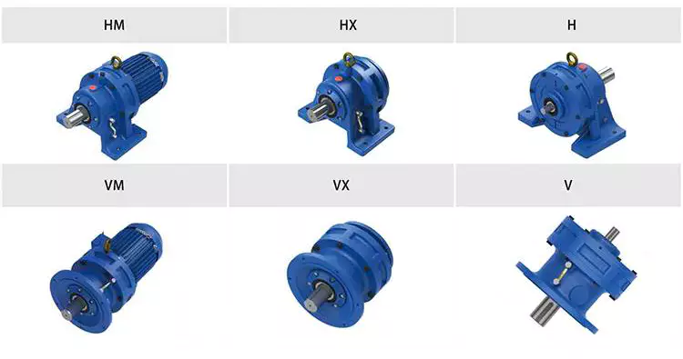
Dynamic and inertial effects
Several studies have been carried out on the static and dynamic properties of cycloidal gears. The study of these effects is beneficial in assisting optimal design of cycloidal speed reducers.
In this paper, the dynamic and inertial effects of a two-stage cycloidal speed reducer have been investigated using the CZPT program package. Moreover, a new model for cycloidal reducers based on non-linear contact dynamics has been developed. The new model aims to predict several operational conditions.
The normal excitation contact force for the cycloid discs of the first and second stage is very similar. However, the total deformation at the contact point is different. This effect is mainly due to the system’s own oscillations. The cycloid discs of the second stage turn around the ring gear roller with a 180deg angle. This angle is a significant contributor to the torque loads. The total excitation force on the cycloid discs of first and second stage is 1848 N and 2068.7 N, respectively.
In order to analyze the contact stress, different gear profiles were investigated. The mesh density was considered as an important design criterion. It was found that a bigger hole reduces the material content of the cycloidal disc and results in more stresses.
Moreover, it is possible to reduce the contact forces in a more efficient manner by changing the geometric parameters. This can be done by mesh refinement along the disc width. The cycloidal disc has the greatest influence on the output results.
The efficiency of a cycloidal drive increases with the increase in load. The efficiency of a cycloidal reducer also depends on the eccentricity of the input shaft and the cycloidal plate. The efficiency curve for small loads is linear. However, for the larger loads, the efficiency curve becomes more non-linear. This is because the stiffness of the cycloid reducer increases as the load increases.
Structure
Despite the fact that it looks like a complicated engineering puzzle, the construction of a cycloidal gearbox is actually quite simple. The key elements are the base, the load plate and the thrust bearing. All these elements work together to create a stable, compact gearbox.
The base is a circular section with several cylindrical pins around its outer edge. The pins are fixed on a fixed ring that holds them in a circular path. The ring serves as a reference circle. The circle’s size is approximately 5mm in diameter.
The load plate is a series of threaded screw holes. These are arranged 15mm away from the center. These are used to anchor external structures. The load plate must be rotated around the X and Y axis.
The thrust bearing is placed on top of the load plate. The bearing is made of an internal diameter of 35mm and an external diameter of 52mm. It is used to allow rotation around the Z axis.
The cycloidal disc is the centerpiece of the cycloidal gearbox. The disc has holes for the pins that drive the output shaft. The holes are larger than those used in output roller pins. The disc also has a reduced eccentricity.
The pins are attached to the cycloidal disc by rolling pins. The pins are made of a material that provides mechanical support for the drive during high-torque situations. The pins have a 9mm external diameter. The disc has a number of lobes and is rotated by one lobe per shaft revolution.
The cycloidal gearbox also has a top cover that helps keep the components together. The cover has a pocket for tools. The top cover also has threads that screw into the casing.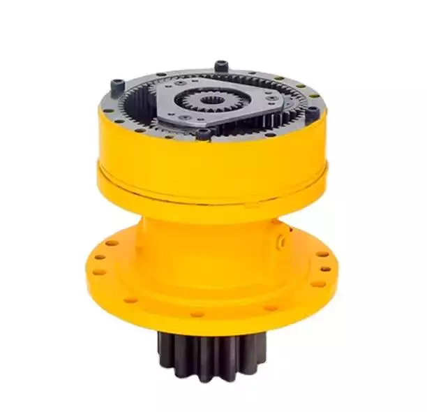
Operation principle
Among many types of gear transmissions, cycloidal gearboxes are used in heavy machinery and multi-axis robots. They are highly effective, compact and capable of high ratios. In addition, they have an overload capability.
Cycloid disks are driven by eccentric shafts that rotate around fixed ring pins. Roller pins of the pin disc engage with holes in the cycloidal disc. These roller pins drive the pin disc and the pin disc transfers the motion to the output shaft.
Unlike conventional gear drives, cycloidal drives have low backlash and high torsional stiffness. They are ideally suited to heavy loads and all drive technologies. The lower mass and compact design of the cycloidal disk also contributes to its high efficiency and positioning accuracy.
The cycloidal disc plays a central role in the gearbox kinematics. It rotates around a fixed ring in a circle. When the disc is pushed against the ring gear, the pins engage with the disc and the roller pins rotate around the pins. This rotating motion generates vibration, which travels through the driven shafts.
Cycloid discs are typically designed with a short cycloid, so that the eccentricity is minimized. This reduces unbalance forces at high speeds. Ideally, the number of lobes on the cycloid is smaller than the number of surrounding pins. This reduces the amount of Hertzian contact stress.
Unlike planetary gears, cycloidal gears have high accuracy and are capable of withstanding shock loads. They also experience low friction and less wear on tooth flanks. They also have higher efficiency and load capacity.
Cycloid gears are generally more difficult to manufacture than involute gears. Cycloid gears are not suitable for stacking gear stages. They require extreme accuracy for manufacturing. However, their smaller size and low backlash, high torsional stiffness, and low vibration make them ideal for use in heavy machines.
Involute gear tooth profile
Almost all gears are manufactured with an involute gear tooth profile. Cycloid gears are also produced with this profile. Compared with involute gears, cycloid gears are stronger and can transmit more power. However, they can also be more difficult to manufacture. This makes them costlier.
The involute gear tooth profile is a smooth curve. It is derived from the involute curve of a circle. A tangent to the base circle is the normal at any point of an involute.
This curve has properties that allow the involute gear teeth to transfer motion in perpendicular direction. It is also the path traced by the end of the string unwrapping from a cylinder.
An involute profile has the advantage of being easy to manufacture. It also allows for smooth meshing despite misalignment of the centre distance. This profile is also preferred over a cycloid tooth profile, but it is not the best in every regard.
Cycloid gear teeth are also made of two curves. Unlike involute teeth, cycloid gear teeth have a consistent radius. Cycloid gears are less likely to produce noise. But they are also more expensive to manufacture.
Involute teeth are easier to manufacture because they have only one curve. Cycloid gears can also be made with a rack type cutter. This makes them cheaper to manufacture. However, they require an expert design. They can also be manufactured with a gear shaper that includes a pinion cutter.
The tooth profiles that satisfy the law of gear-tooth action are sometimes called conjugate profiles. The involute profile is the most common of these. It allows for constant torque transmission.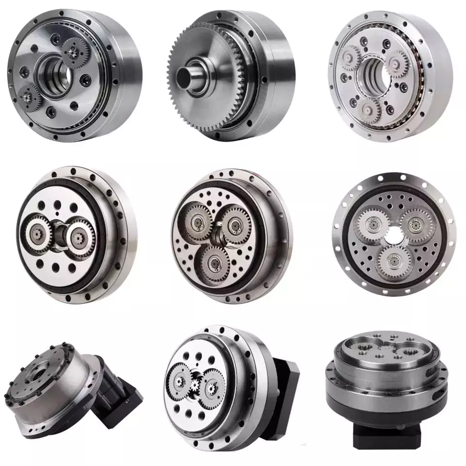
Backlash
Typically, cycloidal drives provide a high ratio of transmission with no backlash. This is because the cycloid disc is driven by an eccentric shaft. During rotation, the cycloid disc rotates around a fixed ring. This ring also rotates independently of the center of gravity.
The cycloid disc is typically shortened to reduce the eccentricity. This helps to minimize the unbalance forces that may occur at high speeds. The cycloid also offers a larger gear ratio than traditional gears. This provides a better positional accuracy.
Cycloid drives also have a high torsional stiffness. This provides greater torsional resilience and shock load capabilities. This is important for a number of reasons, such as in heavy-duty applications.
Cycloid drives also have lower mass. These benefits make them ideally suited for all drive technologies. The design also allows for higher torsional stiffness and service life. These drives also have a much smaller profile.
Cycloid drives are also used to reduce speed. Because of the high torsional stiffness of the cycloid, they also have high positioning accuracy.
Cycloid drives are well-suited to a variety of applications, including electric motors, generators, and pump motors. They are also highly resistant to shock loads, which is important in a variety of applications. This design is ideal for applications that require a large transmission ratio in a compact design.
Cycloid drives also have the advantage of minimizing the clearance between the mating components. This helps to eliminate interference and ensure a positive fit. This is particularly important in gearboxes. It also allows for the use of a load cell and potentiometer to determine the backlash of the gearbox.

editor by czh 2023-01-21